Vortex Steam Flow Meter
$0.00
- Accurately measures mass and volume.
- Designed for safety and reliability
- Adjusts for density fluctuations
- No moving parts, no impulse lines
- Reliable and efficient measurement
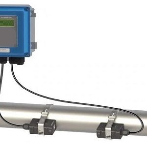
You’re looking for a reliable and accurate steam flow meter, and the Vortex Steam Flow Meter is an excellent choice. This meter uses a unique vortex-shedding technology to measure the velocity of steam flow, providing highly accurate and repeatable results. Its compact and durable design makes it perfect for use in various industrial and commercial settings. The meter is easy to install and maintain and features a large, easy-to-read digital display for convenient data monitoring. Whether working in a power plant, a manufacturing facility, or any other industrial setting, the Vortex Steam Flow Meter will give you the precise and reliable steam flow measurement you need. With its precision and durability, this meter is an excellent investment for any steam flow measurement application. So, it will be a perfect fit for your steam flow measurement needs.
Features for Vortex Steam Flow Meter
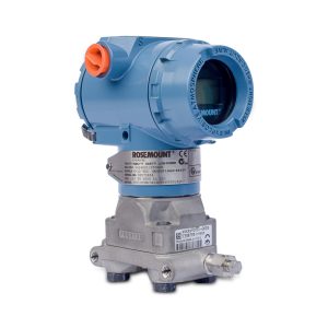
- The Vortex Steam Flow Meter is an all-cast, gasket-free, sealed meter body that eliminates leak points, ensuring the safety and reliability of your operations.
- It can adjust automatically for variations in density, providing accurate measurements even if the thickness of the steam or liquid fluctuates.
- Flow meter does not have moving parts, making it easy to maintain and reducing the risk of process upsets.
- It does not require the installation of impulse lines, making it easy to install and use.
- The advanced technology of the Vortex Steam Flow Meter ensures that it is a reliable and efficient device for any steam or liquid application.
- The design of the flow meter is innovative and user-friendly, making it easy to operate and monitor your operations.
Where to Buy Vortex Steam Flow Meter
They are known for providing durable and reliable products for various industrial applications. They offer a wide range of flow meters and other instrumentation products to help you achieve accurate measurements and keep your operations running smoothly. The Vortex Steam Flow Meter can be purchased from the Instrumentation Control System website.